ADAM is About Advanced Design and
Manufacturing and Cyberspace Product and Service Reviews in our
Virtual Exhibition Hall, Including the Latest News, the Most
Innovative International Products & Services, New Strategies,
R&D, and more...
ADAM: R&D
Article
Ranky, Paul
G.: Some Generic Algorithmic
Solutions to the Problem of Dynamic Scheduling in Flexible
Manufacturing Systems that Operate Globally
Published by ADAM at
http://www.cimwareukandusa.com, © Copyright by CIMware Ltd. UK
and CIMware USA, Inc.
Please feel free to download this paper with
its full contents,
FREE
of charge, but always mention the website:
http://www.cimwareukandusa.com and the author(s) as the
source!
Website:
http://www.cimwareukandusa.com
Email: cimware@cimwareukandusa.com

Go to Welcome Page
Go to ADAM
Address: Paul G. Ranky, Dr.
Techn/PhD, Full, Tenured Research Professor, The Department of
Industrial and Manufacturing Engineering, New Jersey Institute of
Technology, Newark, NJ 07102, USA, Email: ranky@admin.njit.edu
Article
Contents:
Abstract
Go to top
We have to recognize that traditional, mass-produced,
highly-controlled static and rigid design and manufacturing/ assembly
methods cannot cope with the increased amount of information,
knowledge and inferencing requirements of the customers of this
rapidly changing world.
The life cycle of critical design and manufacturing technologies
is increasingly contracting. As a consequence, we need to
mass-customize, be pro-active, and customer driven at a very high
quality and low cost. Furthermore we need to continuously innovate
and improve. We have to accept paradigm shifts at a much faster rate
than ever before, otherwise "somebody else will satisfy our
customers" and consequently "we'll be out of business".
The challenge we face is to narrow the gap between the theory and
the practice, and offer computable methods, tools and technologies,
that will keep enterprises highly responsive to market changes and
produce goods (and services) on demand at a high quality and
relatively low cost in the forthcoming "Knowledge Age". This paper
propagates the above, by putting some light on the challenges, as
well as by offering generic algorithmic solutions to the problem of
dynamic scheduling with integrated tool, fixture, robot hand
management and multimedia support in distributed, lean and flexible
manufacturing and design systems (including flexible assembly systems
employing human operators as well as robots) that operate on a global
basis. Our approach is that we start with the distributed macro level
offering a global overview and then we "zoom in" to the networked
factories, their FMSs, right into algorithms and rules of dynamic
schedules, with multimedia and tool management - ending at the tip of
the tools!
Keywords:
Go to top
Dynamic Scheduling of FMS, FMS/ FAS, Flexible Design,
Manufacturing and Assembly Systems, Tool Management, Robot Hand
Management, Engineering Multimedia, Distributed Enterprise,
Logistics, Global Manufacturing
As a general idea let us suggest that when you
look up the selected website you choose "New Window with this
Link..." in your browser by clicking with the right-hand-side
mouse button (PC) or by keeping the mouse button pressed down (on the
Mac) immediately after you have clicked on the hyperlink. This way
when you wish to "hop back" to the www.cimwareukandusa.com site you
can do it in one step!

Introduction
Go to top
Concepts such as lean and flexible manufacturing, time to market,
total quality management, local design, global manufacture,
concurrent or simultaneous engineering, intelligent design and
intelligent manufacturing systems are widely accepted. These methods
and technologies require multiskilled and well - educated engineers
and managers as well as lean, flexible, and feedback controlled
manufacturing technologies, such as cellular manufacture, CIM,
Concurrent Engineering and FMS run and producing goods based on
customer orders using dynamic scheduling methods between facilities,
plants and shops for all resources, including parts, machines, tools
and fixtures.
Furthermore, it is important to recognize that we are living in an
era when the customers, not the designers or salesmen, are the kings.
Customers require increasingly better products at a lower cost. In
other words, products require continuous improvement and change,
therefore lean, agile and flexible design and manufacture, and the
appropriate level of automation, must be provided throughout the life
cycle of product development, as well as during its maintenance and
finally its de-manufacturing.
The enterprise with a future is a continuously learning
enterprise, that thrives on creating and employing new knowledge
using its own resources as well as by networking and collaborating
with others (i.e. the concept of "1+1=3"), often on a global basis,
using technologies such as EDI (Electronic Data Interchange,
including business as well as engineering data), the Internet and
various Intranets.
Therefore the understanding and the processing methods of data,
information and knowledge and systems are of utmost interest. This is
why we have to focus on multimedia education too. In the education
business the customers are the learners, i.e. students entering
access courses, college and university courses, mature students who
are prepared to study in the evenings at home, or at the University,
or in Open Learning Centers, or most importantly on the job, next to
their cell controllers and CAD computers. Furthermore, there are a
large number of continuing education students and other professionals
seeking new focused knowledge in this rapidly changing and extremely
competitive world.
Before going further, let us spare a few words on terminology. In
our discussions the term system refers to a specific configuration of
objects. Then the term process refers to the pattern of behavior of
an object such that the pattern is composed of a few primitive
constructs. Therefore, a communicating process, such as for example a
module of the dynamic FMS scheduler, is a subsystem of the
environment, and a subsystem is a cluster of communicating
processes.
Some of the
challenges of our dynamically scheduled, highly parallel and
distributed "Knowledge Age"
Go to top
Advances in computers have provided exciting opportunities in Lean
and flexible design and manufacturing, rapid prototyping, Desktop
Publishing and Desktop Design (CAD/CAM), but we are entering now into
a new era of Knowledge Engineering at the desktop, covering all
aspects of the enterprise.
Consider the fact that due to the advance of communications and
automation technologies it is now common, that a product is designed
in one part of the world, manufactured on an other part of the world
(often another continent), assembled again somewhere else and used
(with various minor customization changes) everywhere in the world.
In other words we need to deal with a variety of combinations of
local design and manufacture and global design and manufacture.
In order to attempt to illustrate this "global thinking" with
simple models, please refer to Figure
1 to view the Data-flow Diagram (DFD) of a simplified small -
to - medium size contract manufacturing company. (Note the lack of
any serious design function in this model!). In this diagram ellipses
mean processes, parallel lines are data stores, or data bases and
square boxes are data sources, or data sinks, or sometimes both.
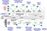
Figure 2 illustrates a more
advanced company model. Note the various feedback loops between
processes, including design and others, as well as the various
internet/ intranet/ satellite links between various processes.
Overall, this company could work well in cyberspace because it has
the communications capabilities!

Please click on the image to view Figure 1
full size

Please click on the image to view Figure 2
full size
As an example for another "globally distributed" solution
Figure 3 illustrates two
companies sharing various functions and processes via the cyberspace
using interactive multimedia based web-techniques. (Note, that we
will discuss the importance of interactive multimedia further
below). The core issue is, that in
the forthcoming "Knowledge Age" multiple facilities and multiple
firms must collaborate and simultaneously compete in a distributed,
global environment. This figure attempts to illustrate with the aid
of data flow diagrams, that there are several multimedia, Internet
and Intranet EDI links possible to fuel design, marketing, flexible
manufacturing and other collaborative, global logistic operations.
Most importantly, one can design at one site and manufacture (and
dynamically schedule) several thousand miles away at an other site
using EDI facilities in such "distributed enterprises". This is
feasible because the available IT technology, and it is cost
effective because of the local logistic supply chains that the
factories in question need to operate successfully.

Please click on the image to view Figure 3
full size
This means several things ([1] to [4]). Most
importantly, we need to:
* Improve the production efficiency
* Improve the responsiveness to market needs and changes
* Reduce cost substantially
* Shorten product life cycles, in particular in the automotive,
semiconductor, electronics, and other high technology industries
Naturally, the gap between theory and practice must be reduced to
solve the above listed problems. Furthermore, one must address the
dynamic and interdependent nature of modern production facilities
that are needed to bridge this gap, as well as that in the new
"Knowledge Age" multiple facilities and multiple firms must
collaborate (and compete) simultaneously (Figure
3 ).
The
distributed model of dynamically scheduled FMSs operating on a global
basis
Go to top
In order to appreciate the importance of the distributed model of
dynamically scheduled FMSs operating on a global basis ([5]
to [12]), let us briefly summarize the differences between
sequential versus distributed processes in such systems with the
view, that by understanding the model we can generalize it and expand
it to help us to understand our distributed enterprise model, that
includes not just flexible manufacturing, but also shared/
distributed/ concurrent engineering, marketing and other functions
too.
By definition, a sequential process is considered to be a
spatially localized event structure that is described by a pattern of
events separated by regular or irregular time intervals. Consequently
the events in such processes or systems are totally ordered.
On the contrary, in a distributed system the processes are
partially ordered and spatially separated in such a way that the
transmission time, T, that is required to transmit a message
between process P(i) and process P(k), is not zero.
Based on the earlier works of Ranky, Lamport, Anger, Chandy,
Mistra, Tanik and Chang ([1 ], [2 ], [29],
[30], [31], [34] to [37]) let us
discuss a new, extended algorithm to illustrate the operation and
messaging processes in our distributed model of dynamically scheduled
lean and flexible design and manufacturing systems operating on a
global basis. In order to simplify the understanding of our model,
let us assume that all processes that are subject to our analysis,
actually occur within the same time frame. (Note, that this
simplification does not effect the generic nature of the algorithm,
but simplifies its understanding at this stage).
As examples, this algorithm works well in a distributed FMS
control environment, in which many cells, machine tools, robots,
AGVs, etc. are dynamically re-scheduled (Figure
4), or in cases where multiple CAD/CAM workstations
concurrently communicate with each other (see Figure
2 and Figure
3 again). In general it works well in a distributed system in
which each process or activity is a model of a subsystem of a larger
system. (In this context consider a dynamically scheduled
workstation, a cell, an FMS system, a CIM factory, or globally
networked CIM factories as various models of subsystems that are part
of a larger system).
Please click on the image to view Figure 4
full size
The logical time mechanism as well as the time stamping technique
used in our algorithm can be used for dynamic resource allocation for
overall FMS dynamic scheduling. In most cases, due to the
just-in-time need (versus e.g. capacity maximization) of such systems
(as FMSs), the priority allocation scheme is on a first come- first
serve basis.
This means that in this priority allocation scheme the resources
that the FMS has in terms of setup, processing, tooling, clamping/
fixturing, material handling, part and tool changing, etc. is to be
dynamically allocated and re-allocated (meaning de-allocated if the
capacity is limited) at instances, represented by events of the time
span analyzed. (Note, that as an example, the shortest possible time
span is typically what it takes to change a pallet for a milling
center, or load/ unload a part for a turning center by means of a
robot. From a dynamic scheduling point of view this is considered to
be the shortest possible time span available for such analysis or
dynamic re-scheduling of the FMS. In practice, this is approximately
5 to 7 seconds for milling centers and around 3 to 5 seconds for
turning centers, meaning that very fast algorithms are needed.
Assuming that the planning horizon allows the luxury to look at a
longer time span, then the sum of the shortest processing time with
allowances for setup, part and tool transportation times is
considered to be the shortest possible time span available for such
analysis (or dynamic re-scheduling).
As examples for the above, consider the following algorithms for
calculating such critical times:
Procedure A
Begin
Sum:=0;
For I:=1 to Task_No do
Sum:=Sum+Completion[I];
MFT:=Sum/Task_No
End;
End (* Proc A *);
Procedure B
SumA:=0;
SumB:=0;
For I:=1 to Task_No do
Begin
Writeln (Print,
trunc(Task[I]:10, y[I]:10:2,
Completion[I]:10:2,
Trunc(Z[I]):8, X[I]:10:2);
SumA:=SumA+Completion[I]*Z[I];
SumB:=SumB+Z[I];
End;
WMFT:=SumA/SumB;
End (* Proc B*);
It is obvious of the above, that as the most important design
criteria of the dynamic scheduler for distributed FMS systems with
integrated tool management is to manage the available FMS resources,
determined at the earliest time stamp (T + d) from among
real-time requests of various concurrent events. Furthermore, this
means that a process P(i) must be able to wait for a request
with the earliest time stamp (T(i) + d(i)).
In practical terms, in real-world dynamic FMS scheduling, a cell
or workstation, or an other resource is not allocated by the dynamic
scheduler to take the next task until there is at least one message
in every queue to the effect that the request with the earliest time
stamp can be selected and at the same time the process can update its
clock.
In order to describe the algorithm, let us define the following
conditions and rules:
1. If a and b are events in the same process
P, and event a precedes event b, then a
"implies" b. (Please note, that in order to make
sure that all readers of this text see the same characters over the
web, even with older (i.e. pre-html 4.0) browsers, instead of the
usual "right arrow character" we use the mathematically correct term
"implies" in our description).
2. If event b is the recipient of the same message
sent by another event (k) as well as event a, then a
"implies" b
3. In all above conditions, the relation "implies" on the
same set of events in a distributed system is the smallest relation
that satisfies each condition. We also assume, that "implies"
is not reflexive.
4. Furthermore, the relation "implies" is transitive,
meaning, that if a "implies" b and if b
"implies" c, then a "implies" c
5. Also note, that events in our model are partially ordered,
meaning, that if neither a "implies" b nor
b "implies" a, then a and b are
two concurrent, or simultaneous events.
Sequencing
events
Go to top
Next, we have to turn our attention to the process of sequencing
events in our distributed model. First, this will be defined by a set
of axioms as follows:
* As the events of the system unfold in real-time, the logical
system clock mechanism (Clock ) should operate without
interruption.
* Let Event = U Event(i) be a set of events in our
distributed model.
* Our system clock, Clock: Event "implies" N
is defined (where N = natural numbers) as the set of logical
clocks for each event a in process Pi as well as for
each process Pi , Clock(i) = Event
"implies" N by letting
Clock(a) = Clock(i)(a)
* If a and b are concurrent events (meaning that
a E Event(i) (read as: event a is an element of
set Event(i)) and that
b E Event(j) ) then it is possible for the event
Clock to have
Clock(a) = Clock(b).
Furthermore to the above listed criteria, the mapping clock
Clock must meet the following system clock condition:
For any events, a and b, if a
"implies" b then Clock(a) <
Clock(b)
The system clock condition is equivalent to the following two
conditions imposed on the process clock:
[Condition_1]: In a process P(i)
if a "implies" b then Clock(i)(a) <
Clock(i)(b)
[Condition_2]: If event b is the
recipient of the message sent by process P(j) and if event
a is the sender of a message by process P(i), then
Clock(i)(a) < Clock(j)(b)
Process
clock conditions
Go to top
In order to meet the two process clock conditions, as defined
above, each process must implement its own logical clock as
follows:
Since there are two consecutive events in a process marking the
start and the end of an information processing activity, at the
occurrence of each event, the logical clock must be incremented by an
integer number that is proportional to the real elapsed time. This
means:
[Rule_1]: Each process P(i)
increments Clock(i) by an integer number that is
proportional to the real elapsed time between the current event
and the immediately preceding event.
[Rule_2]: If event a is the sender of a
message by process P(i )then that message must be time
stamped with the value
T = Clock(i)(a).
If event b is the recipient of a message sent by process
P(j) then the process P(j) must increment its
logical clock Clock(j) to the greater of the value
proportional to the elapsed time between the current event and the
immediately preceding event the value of T + d where
T is the time stamp and d > 1 is
defined with reference to the system time.
It must be noted, that in order to assure, that the concurrency
remains asynchronous, [Rule_1] assures that
[Condition_1] is satisfied and that at the same time, by
means of logical clocks hides the negligible differences between the
current values of the real-time clocks.
Dynamic
scheduling algorithm of FMSs with integrated tool
management
Go to top
The most important operation control activities in FMS/ FAS
identify three levels at which simulation and optimization is
required, prior to, or during FMS/FAS part manufacturing. The three
levels are as follows:
1. The factory level, or business level handled by the business
system of CIM.
2. The FMS off-line level representing scheduling, simulation and
optimization activities prior to loading a batch or a single
component on the FMS, (handled sometimes by the CAM system, sometimes
by the FMS part programming computer).
3. The real-time controlled level handled by the FMS/FAS operation
control system, a dynamic scheduler with integrated tool management
and multimedia support, representing a situation where the parts are
already physically as well as logically in the real-time controlled
environment.
Due to its complexity, a truly integrated approach is required in
designing a production rule base to provide the job description for
the FMS dynamic scheduler. This is because the dynamic system relies
heavily on the knowledge base as represented by the rule base, and an
overly restrictive rule base will lead to inefficient, at times even
wrong, decisions. In other words, such a structure should represent
all the multi-level interactions and their possible precedence rules
that relate to the manufacturing process planning and processing
decisions in an FMS. This turns out to be a difficult task
([13] to [22]). To underline this again, please refer
again to Figure 2 , reminding
you of the fact that we are working with a networked enterprise,
Figure 3 illustrating
again that enterprises can be globally linked and distributed, and
Figure 4 showing a relatively
complex FMS with all its crucial process capabilities that should be
reachable globally).
Rules are nothing but representations of constraints. Various
types of constraints were studied. It was also realized at an early
stage of the development that a user friendly, ionized,
multi-windowed interactive multimedia with a graphics interface, with
videos and photographs must support the process of building up the
production rule base. (Note that further research is currently being
carried out by the author in to representing FMS process planning and
job control knowledge.)
It should be underlined, that the application of multimedia at
this level is extremely beneficial in terms of part program
preparation, teaching/ training operators on setting up parts,
fixtures, tools, machines, for troubleshooting, for regular
maintenance, at CNC level programming and other tasks (Figure
3).
In order to get acquainted with the system design concepts of our
validated and tested FMS dynamic scheduler let us discuss a
simplified, commented example that illustrates the way parts get
processed using various resources of the FMS, including the option of
dynamic re-routing without any disruptions to the system. (Please
note, that one of the most important benefits of a "well designed"
FMS over a transfer line is this, often misinterpreted, dynamic
re-routing capability).
Let us suggest that as you read the algorithm below,
simultaneously open Figure
4 in the browser in a separate window by choosing
"New Window with this
Link..." by keeping the mouse button pressed down
immediately after you have clicked on the hyperlink.
BEGIN FMS_Part_program/ID Code
of this program: A121297
(* Note that this is the top level of the
FMS part program. This program guides all major pre-programmed
activities of the FMS dynamic scheduler with its integrated tool
management system and interactive multimedia interfaces (where
applicable). It is basically a structure, rule oriented job
description on what the FMS should do with a certain part number
in the FMS. (i.e. Note, that not just one machine, or workstation,
or cell, but the whole system is programmed this way!)
It describes all pallet level, i.e. setup
and operation level programs, including pointers to CNC code, in
the part program database, pointers to the tooling and clamping/
fixturing needs, in the tool management database, probing and
assembly robot hand needs and others, including exactly what is
needed, at which workstation, or cell, and the data on when is the
resource needed - note, that time is calculated here relative to
the completion time of the current process on the designated,
programmed resource. The real-time system clock follows the time
stamping rules described earlier *)
BEGIN Pallet_program/Code: No.1,
Pallet_code: P1; Part_code: Part ABCxyz
(* Note that part/ pallet setup data is
stored at this level. i.e. the workpiece, or part and the pallet
and clamping/ fixturing devices are specified for the dynamic FMS
scheduler. Furthermore note, that as a general principle these ID
numbers act as pointers to the actual data - in this case part and
fixturing/ pallet data - stored in the appropriate part,
fixturing/ pallet databases of the FMS system.
This enables all the checks the dynamic
FMS scheduler must perform before issuing the EXECUTE (real-time)
instruction to the FMS hardware, using the current time - as per
the stamped clock time *)
EXECUTE_operation/ Code: No1,
Tool_file P1_No.1_T01;
(* Note that tooling data for each
operation is stored at this level in a tool file, obtained from
the CNC part program, or a high level CAM programming package.
This enables the FMS dynamic scheduler to compare the actual
contents of the CNC tool magazine with the desired, or programmed
need - given here.
If there is a discrepancy an automated
multimedia REPORT is generated to fix the problem as soon as
possible. If it is not possible, e.g. because the desired target
machine/ cell is busy or broken down, the next alternative is
chosen - see <Condition true/ false below *)
EXECUTE _operation/ Code: No2,
Tool_file P1_No.1_T02;
IF <Condition true>
THEN
(* Note that a condition, true/ false,
analysis can mean resource availability check, or a condition
relating to priority change, or others.
A resource availability check typically
includes the following: Is the machine up and running? Is it
available/ or busy? Are the appropriate tools in its magazine? Is
the final checksum OK to load a palletized part and execute the
program? Do we need to perform secondary optimization at cell
level, and re-schedule the cell input queue ? , and others
*)
BEGIN
EXECUTE _operation/ Code: No3,
Tool_file P1_No.1_T08;
EXECUTE _operation/ Code: No4,
Tool_file P1_No.1_T06;
(* More alternative operations can be
described here...Note, that alternative operation specifications
at this level represent built-in redundancy for alternative
choices that the FMS dynamic scheduler can take in order to
complete the job on due date or earlier.
This is an excellent technique to
increase the decision space and "give more room" and often time
for the real-time dynamic scheduling system to complete the
desired task. This feature will in most cases increase the
productivity of the FMS. It must be underlined though, that the
issue is to complete jobs on due date, not to fully utilize the
capacity of the FMS, and by doing so downgrade it to a transfer
line... as it happens in some cases in industry... *)
END
ELSE
BEGIN
EXECUTE _operation/ Code: NoA3,
Tool_file P1_No.2_T04;
EXECUTE _operation/ Code: NoA4,
Tool_file P1_No.7_T12;
END;
END Pallet_program/Code: No.1,
Pallet_code:P1;
BEGIN Pallet_program/Code: No.2,
Pallet_code:P2;
(* Note that this could be another setup,
or even an alternative setup for the same part. Setup data is
stored at this level. i.e. pallet and fixture. We do not detail
it, just its structure *)
EXECUTE _operation/ Code: No1,
Tool_file P2_No.2_T01;
(* Note that tooling data for each
operation is stored at this level in a tool file, obtained from
the CNC part program, or a high level CAM programming package,
such as GNC, etc. *)
CASE OF <Condition_1 true>
THEN
(* Note that a condition, true/false,
analysis can mean resource availability check, or a condition
relating to priority change, or others. Also note, that we have
introduced a new way of describing conditions with the Case...Of
statement *)
BEGIN
EXECUTE _operation/ Code: No2,
Tool_file P2_No.2_T012;
EXECUTE _operation/ Code: No3,
Tool_file P2_No.2_T09;
END
CASE OF <Condition_2 true>
THEN
(* Note that a condition, true/false,
analysis can mean resource availability check, or a condition
relating to priority change, or others *)
BEGIN
EXECUTE _operation/ Code: NoA3,
Tool_file P2_No.2_T04;
EXECUTE _operation/ Code: NoA4,
Tool_file P2_No.2_T12;
(* More alternative operations can be
described here...*)
END;
(* More alternative operations can be
described here...*)
END Pallet_program/Code: No.2,
Pallet_code:P2;
(* More pallet programs can be described
here before inspection *)
BEGIN Pallet_program/Code: No.3
Inspection, MUST go onto Machine ID#: CMM1
(* Note, that this command "MUST go onto
Machine ID#..." will force the FMS dynamic scheduler to select the
designated machine. In this case the Co-ordinate Measuring
Machine. By invoking this command, the dynamic scheduler in
collaboration with the FMS tool management system will check the
number and type of probes needed/ available at Machine ID#: CMM1
(actually it will check the logical probe ID#s in its automated
probe changer).
This will make sure, that by the time the
part gets to this machine, all conditions are fulfilled. If for
any reason at current time this is not the case, the FMS dynamic
scheduler will have to call upon the tool management systems
reporting routines and instruct the tool manager on duty, or
automatically, to load up the CMM with the necessary tools/
probes.
Note, that the actual probe IDs are
listed in the actual CMM program headers below!
Note that setup data is stored at this
level. i.e. pallet and fixture. Inspection is carried on this part
and this pallet. Pallets can be loaded automatically onto
Co-ordinate Measuring Machines *)
EXECUTE _operation/ Code: No1, Tool/
Probe_file P1_No.1_T012;
(* Note that probing/ tooling data for
each inspection/ test operation is stored at this level in a tool
file, obtained from the CMM part *)
FEEDBACK & CORRECT
(* The FEEDBACK & CORRECT instruction
is a very powerful command, since it will instruct the FMS dynamic
scheduler that upon an out of tolerance measurement it should
check - in the given order - on the responsible surface of the
part, then the operation ID#, then the tool ID#, then the tool's
actual set correction data (e.g. length and radius), identify the
Machine/ workstation ID#, Cell ID#, and even report on exactly
where the responsible tool is at current time - using the
reporting function below.
This will enable automated tool length
correction at CNC level, automated sister tool selection at CNC
tool magazine level and automated error messaging at FMS system
control and tool management levels - using multimedia - to all
interested parties. Note, that the detailed data flow and control
system of this automated, self correcting feature was a very novel
concept in the early days of FMS and even today it is a rarely
found option. Furthermore it underlines the importance of self
correcting, intelligent machines integrated into a system such as
an FMS *)
REPORT
(* This command automatically creates a
multimedia report, stores it in the FMS System History Database
and sends it to all parties that need to act immediately, as well
as to those who must be kept informed only *)
EXECUTE _operation/ Code: No2, Tool/
Probe_file P1_No.2_T002;
(* Note that probing/ tooling data for
each inspection/ test operation is stored at this level in a tool
file, obtained from the CMM part *)
FEEDBACK & CORRECT
(* More FEEDBACK & CORRECT activity
can be generated here - if requested - in principle, as described
above *)
REPORT
(* More multimedia REPORT generation can
be activated here - if requested - in principle, as described
above *)
EXECUTE _operation/ Code: No3, Tool/
Probe_file P1_No.3_T006;
(* Note that probing/ tooling data for
each inspection/ test operation is stored at this level in a tool
file, obtained from the CMM part *)
FEEDBACK & CORRECT
(* More FEEDBACK & CORRECT activity
can be generated here - if requested - in principle, as described
above *)
REPORT
(* More multimedia REPORT generation can
be activated here - if requested - in principle, as described
above *)
END Pallet_program/Code: No.1,
Pallet_code:P1;
(* Further alternative pallet programs
can be described here...*)
(* Automated / manual assembly
instructions could follow here in principle in a similar structure
to the above *)
END FMS_Part_program
The virtually
random part scheduling aspects of the system
Go to top
What can be easily recognized of the above structure, is that to
be truly flexible, the FMS/ FAS system should be capable of making
real-time control decisions that include dynamic scheduling, variable
part routing and fast secondary optimization (meaning the reordering
of parts at input queues of cells).
A system such as this which allows virtually random part
scheduling can demonstrate the true flexibility of the FMS/ FAS
concept. Within this overall goal, the secondary objectives are:
1. To show the general applicability of production rule bases and
also how this new concept can be extended to other aspects of
CIM.
2. Develop the system as a component in the overall control
structure of an integrated CIM system. Hence, the system should be
modular and integratable with other systems.
There are two distinct aspects to the development of such a
system:
1. The interactive multimedia interface to build a production rule
base. Note that the real expert on the shop floor is often not a
scheduling specialist. Nor is he expected to be familiar with how to
use a rule based system. Hence this component of the system should
comprise a very friendly graphic interface which shows the rule
structures as they are built up. This sub-system could generate a
file e.g. in a simple structured multimedia format, which can be
understood both by shop floor managers and by engineers.
These files, constituting the production rule base, will be
accessed by the dynamic scheduling program, which will choose from
different candidates depending on the real-time status of the FMS and
the processing needs sent in the form of orders by the business
processing system of CIM.
2. The dynamic FMS scheduling program. This program accesses the
rule base and chooses from the alternative production routes offered,
and makes real-time control decisions based on fast secondary
optimization well as tool/ fixture/ machine (resource)
availability.
The overall
specifications of the FMS dynamic scheduler can be summarized as
follows:
Go to top
At any instant of time during a given period of time, such as a
shift:
1. The system should be capable of interpreting and evaluating the
production situation by reading FMS system status data via the
distributed FMS data processing network, from the cell controllers in
real-time. (It should also display this status in a readily
understandable way, using multimedia, if required).
2. It should read and evaluate the current dynamic (transient)
input data which may include breakdowns (e.g. tool breakage at a
cell, or the breakdown of the entire cell, or the material handling
system, etc.).
It should cope with job priority changes, job deletions and with
the rearrangement of part input queues and buffer stores. (This data
should be used together with the predetermined off-line operation
control input data in order to generate a task for any required
instant of time).
3. It should access the variable route part program data base
(i.e. the production rule base) along with other manufacturing data
to schedule the various jobs from the job list on different cells
using a simple built-in secondary optimization routine. (If required,
the dynamic schedule, showing variable routes for this instant of
time should be displayed).
4. In case of an error in the operation of the FMS or in this
system, and if either of these is irrecoverable, appropriate messages
must be generated. A self-learning, expert diagnostic module should
be incorporated which could learn from such failures and suggest
different ways of changing or updating the rule base.
5. Relevant statistical information and schedule evaluation
criteria based on the operations during the particular shift should
also be generated as part of this system.
6. The interactive multimedia user interface should be such that
even a non-technical shop-floor worker should be able to
supervise/operate the real-time operation control system.
7. The system should be modular in such a way that at each
sub-system level of implementation any of the sub-system modules
should consist of two layers, these being:
* The top level layer, which is FMS architecture
independent, i.e., allows programming at a generic level that can
work in virtually any truly flexible FMS architecture.
* The installation specific layer itself should be such that
the FMS could be expanded and modified without affecting the rest
of the system, i.e., by localizing the implementation specific
details here in this layer, the rest of the module is hidden from
these details.
Furthermore the dynamic FMS scheduling system with integrated tool
management should incorporate procedures such as DELETE workpiece
from any production route and/or the buffer store, WAIT with the
production of a particular workpiece, (because the system is not
capable of accepting further components for the time being), ASK the
status of a component, REARRANGE any production route in real-time
because of a break down or maintenance, and others.
The WAIT
procedure
Go to top
The WAIT procedure for example could be
implemented using this algorithm:
if the production route can be loaded with further
components (in other words if the queue is not full yet) and/or if
there is a free place in the buffer stores,
then the part should be placed logically and physically
as soon as possible into the production route,
else the part should wait in the automated
warehouse, or, if already delivered to the system, in a free
buffer location, close to the cell.
The DELETE
algorithm
Go to top
As a further example, let us show the way
the DELETE algorithm could be designed:
if the processing of the workpiece in any of the
possible production routes is deleted,
then remove the workpiece logically from the production
queue and physically from the buffer store without interrupting
the continuous production of the system.
The ASK
algorithm
Go to top
Finally, the ASK algorithm could be as
follows:
if the dispatcher and/or subsystem sends a request
for workpiece status,
then list those FMS cells and selected routes which the
component has passed through and also those which are planned to
be met in the current schedule. Upon request provide accurate,
actual due date (time) and resource related information.
It is clear from these algorithms that, for each possible
manufacturing route, two lists are required: a waiting list of
workpieces to be manufactured on each selected route, gained as a
result of the frequent simulation of the system, and the current
status description of the availability of the system, gained using
real-time status information.
Buffering
issues
Go to top
Normally components waiting to be manufactured via the same route
in the FMS should be taken one-by-one from the front of each queue
(FCFS, first come first serve) unless otherwise programmed, until
there are no components in the queue, but the rearrangement of
components in queues should also be allowed using different
scheduling rules. This feature is important if a job must be
processed in the shortest throughput time, or in "panic situations"
when the system needs to be rescheduled or recover quickly.
Having allowed for real-time alternatives and for re-scheduling
logically and/or physically existing queues, the program must keep
track of the number of parts with which a production route can be
loaded and must also know the number of workparts already accepted
for production for each route.
Most FMSs have some part buffering capability (see Figure 5
again). This may not be for scheduling reasons, but for
technological, i.e. process planning reasons (e.g. the part must cool
down somewhere before an accurate inspection procedure is performed).
Some level of buffering is useful and necessary because of
reliability reasons. (The actual number of buffer store locations
should be established on the basis of simulation and experience.)
Cells often have some buffers too (e.g. imagine a chain type
pallet magazine of a milling cell. Note that the ideal situation is
when there is one AGV input and one output docking station for each
cell). The reason for this is that by providing a part in the input
queue of the cell just before the currently processed part is
finished at the particular cell, the cell is kept running at its
highest efficiency level, since time is only "wasted" for part
changing, typically lasting only 5-7 seconds. The other important
point to note is that well-designed part buffers offer a direct
access pickup/load facility, making the rescheduling process in the
queues short, simple and dynamic.
What is
Interactive Multimedia and why is it important in FMS?
Go to top
Interactive multimedia combines and integrates text, graphics,
animation, video and sound. It enables learners to extend and enhance
their skills and knowledge working at a time, pace and place to suit
them as individuals and/or teams and should have a range of choices
about the way they might be supported and assessed.
In other words:
* The student has a choice and the freedom to learn
* He, or she is supported by the multimedia based learning
materials and technology
* The tutors are creating an effective, enjoyable learning
environment and infrastructure
Interactive multimedia is essential for all operators, engineers,
managers, etc. to be able to integrate with, operate within and
partially control the typically highly computerized and increasingly
complex systems we all have to work with. As an example, an FMS is a
highly automated, distributed and feed-back controlled system of
data, information and physical processors in which decisions have to
be taken real-time.
This is only possible if all information processors (including the
human resources of such systems) are "well informed", meaning that
they have the exact information at the exact time, format and mode
they need it to take responsible decisions within given time
constraints ([27], and [32] to [33]).
Figure 5 illustrates one of
the many cell operator support, educational, training, quality
control, production control, maintenance and other application
opportunities of multimedia in
FMS).
The
integrated, multimedia supported FMS/FAS tool management
system
Go to top
The design of an FMS/FAS (Flexible Manufacturing/Assembly System)
tool management system incorporates a vast amount of analysis and
system development work. It must be done by a team of process and
industrial, manufacturing systems and design engineers as well as
data processing staff, headed by an experienced team leader who
understands not only the data management problems but also the
operation control and process planning aspects of FMS/FAS systems,
within the CIM environment.
When designing the FMS/FAS tool management system one should
consider the following steps:
1. Collect all current and possible future user and system
requirements.
2. Analyze the system (i.e. the data processing and the FMS/ FAS
hardware and software constraints).
3. Design an appropriate data structure and data base for
describing tools (and/ or robot hands, probes, sensory-based
inspection and assembly tools, etc.).
4. Specify and design programs, and query routines and dialogues
that are capable of accessing this data base as well as communicating
with the real-time production planning and control system of the FMS/
FAS.
Probably the most important question to be answered before
starting to design an FMS tool management system and a data base is
"Who" is going to use the data, "When" and "For what" purposes in the
particular system ?
Tooling data in FMS, are typically going to be used by several
sub-systems as well as by human beings. These are as follows:
* The production planning sub-system.
* Process control.
* Part programming.
* Tool preset and tool maintenance.
* Tool assembly (manual or robotized).
* Stock control and material storage.
For example, the production planning system has to be informed in
real-time about the availability of tools in stock, as well as about
the current contents of the tool magazines of the machine tools (in
the case of Flexible Assembly Systems the robot hands in the
End-of-Arm-Tool magazines) otherwise it will not be able to generate
a proper production schedule.
It must be noted that the real-time aspect is important because
tools are changed in the magazines of machines, (or cells) not only
because they wear, but also because different part programs may need
different sets of tools. (The actual tool changing operation is done
in most cases by manipulators or by robots. The tool magazine
loading/ unloading procedure is performed mostly by human operators,
sometimes by robots or special purpose mechanisms, such as a tool
shuttle).
Both the process control and the production planning systems have
to update any changes and act in real-time, otherwise the operation
of the system can be disrupted.
From the FMS/FAS tooling and tool management points of view one
must emphasize the links between the CAD system, in which the parts
are designed (using design for manufacturing principles), and the CAM
system, where the FMS part programs are written. Typically, an FMS
part programmer analyses the CAD output (i.e. the design drawings of
the component to be manufactured on the FMS), the fixturing, the
different setup (i.e. work mounting) tasks, as well as the necessary
operations, their alternatives, the required tools and finally a
precedence list of the resources (i.e. the possible candidates of
processing stations, or cells, or machines). (Note that the actual
selection of these candidates should be done real-time by the dynamic
scheduler).
The real-time data bases and software systems are also important,
since they provide the reports and status information that are needed
for the smooth operation of the FMS. (In particular, its dynamic
scheduler and other subsystems such as maintenance should be
emphasized here.) The tooling system related tasks are divided into
two levels, the first being TOOL PREPARATION, which is
typically an off-line operated service/support activity (and area, or
station), and the second being REAL-TIME TOOLING activities
(usually situated physically inside the real-time controlled
FMS).
We now discuss both of them in more detail.
As explained earlier, the output of the CAM system is a production
rule base. This is the knowledge the FMS needs to produce each part.
In this production rule base, amongst others, tools are assigned to
each operation. The tool codes are selected by the FMS process
planner, or automatically assigned by a process planning system, and
are obtained from the tool data base. On the basis of the requested
tools a list is sent via the network to the Tool Preparation
Facility, or Station, where the actual tools are prepared (i.e.
assembled and preset) and stored in an appropriate way, such that the
material handling system of the FMS - typically AGVs, or a special
purpose tool shuttle can pick them up.
The tool preparation station also deals with other activities,
among which the most important are as follows:
* Tool service and maintenance.
* Tool assembly to orders (as it is necessary to replace worn
tools).
* Tool preset, tool inspection and adjustment
* Real-time tool pickup and tool transportation organized to serve
the needs of the real-time FMS.
The tool preparation station receives its orders, initially
originated by the CAD data processing system via the FMS network and
technically specified by the CAM system in the form of a production
rule base. Order data arriving at the tool preparation station
includes:
* Part orders (consisting of part codes and quantities). Note that
this is a very important data set for the real-time FMSdynamic
scheduler too.
* Notification of when the parts are physically available for FMS
processing, representing a due date for tool preparation.
* A priority order (note that this can change because of some
real-time changes in the system, thus this station must be able to
cope with this task too).
* The portion of the production rule base, describing the
requirements regarding tool preparation.
The tool preparation station keeps in touch with the real-time FMS
system, as well as with the rest of the system, by feeding back
important tooling system related data relating to:
* Stock reviews (regarding tools).
* FMS status report (regarding tools).
* Part priority status reports (in case dynamic changes must be
performed in the FMS which have an effect on tooling needs and tool
preparation due dates).
The Real-time part of the FMS tool management system must deal
with the following tasks:
* It must handle the application of tools for a variety of
processes as defined in the production rule base and assigned
real-time to the FMS/FAS resources by the dynamic scheduler.
* It must provide data to control the transportation of tools and
tool magazines within the FMS.
* It must provide information to perform and supervise tool
changes and tool magazine changes at all levels.
* It must be notified of tool inspection results (e.g. in the case
that it finds a worn out tool as a result of an inspection procedure
it must generate a command that would instruct the tool magazine
update system to change the tool in question in the appropriate tool
magazine).
* It must provide information in the case of emergency, e.g. if a
tool breaks.
* It must provide the necessary interfaces and data to perform
diagnostic/recovery operations, preferably using diagnostic expert
systems.
Finally, let us underline an important feedback loop starting at
the real-time system, and ending at the tool preparation station,
which contains the real-time tool status, wear and part priority
information. This data is often useful to those people and/or system
software systems that deal with the generation of the production rule
base. It is also a very useful data set for FMS designers, since a
lot of data which would previously have been lost is going to be
saved in this way.
The tool preset station in the Tool Preparation unit must be able
to inform the process control system about tool preset and offset
data, preferably via a digital tool preset unit linked directly to
the data processing network of the FMS. Note that the final
adjustments, i.e. the x, (y) z tool length correction, have to be
performed at the tool preset station or at the machine, if the
machine is capable of performing this operation. Note that length and
diameter values are often set at the cell prior to the first
operation using that tool, as well as between operations using the
real-time operated tool at the machine, in order to check tool
adjustments and tool wear.([33])
Regarding the rest of the tooling data it must be mentioned that
when writing FMS part programs, one must know the actual sizes of
tools and their characteristics and behavior in different conditions.
Tool geometry data is also used when checking for tool collision by
graphics simulation in the CAD/CAM environment.
Conclusions and
Summary
Go to top
We are moving into the "Knowledge Age" when competitive advantage
cannot be maintained without continued and sustained commitment to
innovation, research and continuous creation and application of new
knowledge.
In terms of corporate investment, the financial stake involved in
turning good quality, flexible, Open Access Education and research
into competitive advantage is enormous. As many examples show in
Europe, United States, Japan, Asia and elsewhere, entire nations'
future and wealth (both intellectual and material) depend on the
quality of education provided to learners. This means that the wrong
education, research and development strategy for product design,
manufacture and management can easily spell disaster.
To summarize, one should realize that FMS scheduling cannot be
studied, analyzed and designed in isolation from the distributed,
lean and flexible CIM environment, because it simply would not work
in practice. In other words, it must be part of an overall production
control and management strategy based on fundamentally JIT oriented,
"pull" versus "push type" production control methods, capable of
considering all affected resources (i.e. machines, tools, fixtures,
human operators, etc.) and changing dynamically according to
real-time requests.
Acknowledgments
Go to top
I hereby would like to express my thanks to NJIT, New Jersey
Institute of Technology, The University of East London (UK), the Ford
Motor Company, Hitachi Seiki, FESTO, Denford Machine Tools,
Rolls-Royce Motor Cars, Lucent Technologies, Aircruisers, NSF, DARPA,
General Motors, Hughes, The US National Guard, The New Jersey
Technology Council and the United States Department of Commerce for
their continuous support of my research, industrial and educational
projects.
References and
Bibliography
Go to top
[1] Ranky P.G., The Design and Operation of FMS (IFS
(Publications) Ltd. and North Holland), p. 348, 1982.
[2] Ranky P.G., Computer Integrated Manufacturing
(Prentice-Hall International) p. 528, 1985.
[3] Ranky P.G., A Program Prospectus for the Simulation,
Design and Implementation of Flexible Assembly and Inspection Cells,
International FMS Conference at The University of Michigan, Ann
Arbor, 1986.
[4] Ranky P.G. and P H Francis: Design and Solid Model
Simulation of Generic Assembly Cells and Systems, Japan-USA Symposium
on Flexible Automation, 1986, Osaka, Japan.
[5] Ranky P.G., End of Arm Tool Management System for
Robotized Assembly Lines, Robots West Conference, SME, Long Beach,
CA, 1986.
[6] Ranky, P.G.: An Operation Control Strategy of FMS,
International Conference on Productivity Research, ICPR'87, The
University of Miami, 1987.
[7] Ranky P.G.: Real-Time Quality Control Feedback Loops
in CIM Environment, Automated Inspection and Product Control
Conference organised by IFS Conferences and IITRI, Chicago, 1987.
[8] Ranky, P. G: Libreria Software FMS (An FMS Software
Library), PIXEL (Computer Graphics, CAD/CAM, image processing), Vol
5, No 1, 1984, pp 49-54 (in Italian).
[9] Ranky P.G.: FMS in CIM (Flexible Manufacturing Systems
in Computer Integrated Manufacturing), ROBOTICA, Cambridge University
Press, 1985, Vol 3, pp. 205-214
[10] S Y Nof, M M Barash and J J Solberg: Operational
control of item flow in versatile manufacturing systems.
International Journal of Production Research, 17 479-489., 1979
[11] J Pasquier: High level simulation of flexible card
assembly lines. Research Report RC-10881, IBM Thomas J. Watson
Research Center, Yorktown Heights, New York, USA.
[12] M L Pinedo et al: Sequencing in a flexible assembly
line with blocking to minimize cycle time. Proceedings of the Second
ORSA/TIMS Conference on Flexible Manufacturing Systems: Operations
Research Models and Applications, (Amsterdam: Elsevier Science
Publishers B.V.) pp. 499-508. 1984
[13] R V Rachamadugu et al: Real-time scheduling of an
automated manufacturing center. Proceedings of the Conference on
Real-Time Optimisation in Automated Manufacturing Facilities,
National Bureau of Standards, Gaithersburg, Maryland, USA, pp.
293-316. 1986
[14] T J Schriber and K E Stecke: Machine utilizations and
production rates achieved by using balanced aggregate FMS production
ratios in a simulated setting. Proceedings of the Second ORSA/TIMS
Conference on Flexible Manufacturing Systems: Operations Research
Models and Applications, (Amsterdam: Elsevier Science Publishers
B.V.) pp. 405-416. 1986
[15] An AI Approach to Schedule Generation in a Flexible
Manufacturing System, Sheldon Shen and Yih-Long Chang, The Ohio State
University, USA. Proceedings of the Second ORSA/TIMS Conference on
Flexible Manufacturing Systems: Operations Research Models and
Applications, edited by K.E. Stecke and R. Suri, Elsevier Science
Publishers B.V., Amsterdam, 1986 - Printed in The Netherlands.
[16] Y Kuratani et al: A pre-computational report on job
shop simulation research. J. Oper. Res. Soc. Japan 2, 145-183
(1960).
[17] E LeGrande: The development of a factory simulation
system using actual operating data. Management Tech. III(1), 1-19
(1963).
[18] A Ashour:Sequencing Theory. Lecture Notes in
Economics and Mathematical Systems. Springer-Verlag, Berlin
(1972).
[19] S Eilon et al: Job shop scheduling with due date.
Int. J. Production Res. 6(1), 1-13 (1967).
[20] S E Elmaghraby: The machine sequencing problem-review
and extensions. Naval Res. Logistics Quart. 15(2), 205-232
(1968).
[21] J Erschler et al: Periodic loading of flexible
manufacturing systems. In: Advances in Production Management Systems
(Elsevier Science Publishers IFIP) 1984
[22] Ranky P.G.: Dynamic Simulation of Flexible
Manufacturing Systems (FMS), Applied Mechanics Reviews, Special FMS
issue, ASME (The American Society of Manufacturing Engineers),
1986.
[23] Ranky P.G.:Tool management tasks in flexible
manufacturing systems (FMS). NAMRC XIV (North American Manufacturing
Research Conference), Minnesota, USA, 1986.
[24] Ranky P.G.: End of arm tool management system for
robotized assembly lines. Robots West Conference, Long Beach,
California, USA, 1986
[25] Suri, rajan, Desiraju, Ramakrishna: Performance
analysis of Flexible Manufacturing Systems with a Single Discrete
Material - Handling Device, The International Journal of Flexible
manufacturing Systems 9 (1977) p. 223-249, 1997
[26] Caprihan, Rahul and Wadhwa, Sughash: The Impact of
Routing Flexibility on the Performance of an FMS - A simulation
study, The International Journal of Flexible manufacturing Systems 9
(1977) p. p. 273-298, 1997
[27] Ranky, P G: An
Introduction to Total Quality and the ISO90001 Standard An
Interactive Multimedia Presentation on CD-ROM with off-line Internet
support by CIMware (IEE and IMechE Approved Professional
Developer). Multimedia design & Programming by P G Ranky and M F
Ranky, http://www.cimware@cimwareukandusa.com
[28] Ranky, P G: Computer
Network Architectures for World Class CIM Systems, CIMware, ISBN
1-872631-01-0, 231 p. http://www.cimwareukandusa.com
[29] Ranky, P G: Manufacturing
Database Management and Knowledge Based Expert Systems, CIMware
Ltd., ISBN 1 872631-03-7, 240 p http://www.cimwareukandusa.com
[30] Ranky, P G: Flexible
Manufacturing Cells and Systems in CIM, CIMware Ltd., ISBN
1-872631 02-9, 264 p. http://www.cimwareukandusa.com
[31] Ranky, P G: Concurrent
/Simultaneous Engineering Methods, Tools and Case Studies,
CIMware Ltd., ISBN1-972631-04-5, 264p.
http://www.cimwareukandusa.com
[32] Ranky, P G: An
Introduction to Concurrent/ Simultaneous Engineering, An Interactive
Multimedia Presentation on CD-ROM with off-line Internet support
(650 Mbytes), published by CIMware, Multimedia design &
programming by P G Ranky and M F Ranky,
http://www.cimware@cimwareukandusa.com
[33] Ranky, P G: An
Introduction to Flexible Manufacturing, Automation and Assembly, An
Interactive Multimedia Presentation on CD-ROM with off-line Internet
support (650 Mbytes), published by CIMware. Multimedia design
& programming by P G Ranky and M F Ranky,
http://www.cimware@cimwareukandusa.com
[34] Anger, F D: On Lamport's Interprocessor Communication
model, ACM Transactions on Programming Languages and Systems, 11(3):
404 - 417p.
[35] Lamport, L: Time. Clocks and the Ordering of Events
in a Distributed System, Communications of ACM, 21(7) 558-565 p.
[36] Chandi, K and Mistra J.: Asynchronous Distributed
Simulation via a Sequence of Parallel Computations, Communications of
ACM, 24(4) 198-406 p.
[37] Tanik M M and Chan E S: Fundamentals of Computing for
Software Engineers, Ginny's, 1995, p. 251.
Go to top